Circuit Breaker Single Line Diagram Symbols | A single line can show all or part of a system. Circuit symbols are used in circuit diagrams (schematics) to represent electronic components. It has only one hot wire & when there is any overload or short circuit it. Though these names are not approved as standard notations, they are. In the single line diagram, the system component is usually drawn in the form of their symbols.
Circuit symbols are used in circuit diagrams (schematics) to represent electronic components. It has only one hot wire & when there is any overload or short circuit it. A single line can show all or part of a system. Symbol of the elements of electronic component used in circuit. The single line diagram is also called the blueprint of electrical system analysis.

Since the electrical standards adopted by various. Single line symbols electrical symbols used to represent various electrical devices for usages in electrical schematic design. Single pole single throw, and its abbreviation—in this case, spst. Lets go through a industrial single line diagram. In complex diagrams it is often necessary to draw wires crossing even though they are not connected. It has only one hot wire & when there is any overload or short circuit it. Lightning arresters are the protective devices used for protection of. Your electrical panel is full of circuit breakers running through the panel, and the main circuit breaker serves an especially important function. The circuit breaker, transformer, capacitor, busbar, etc. All circuit symbols are in standard format and can be used for drawing schematic circuit diagram apart from the circuit symbols, each device is also designated a short name. Electrical circuit schematic symbols are graphical sign, that is used to design electronic, electrical circuit schematic diagram. There is a quite adequate collection of symbol for electrical, electronic circuit. I am starting to create our default symbol library.
This single line diagram can be used to easily design a. It has only one hot wire & when there is any overload or short circuit it. Comparison of nema and iec schematic diagrams. Single pole single throw, and its abbreviation—in this case, spst. I am starting to create our default symbol library.
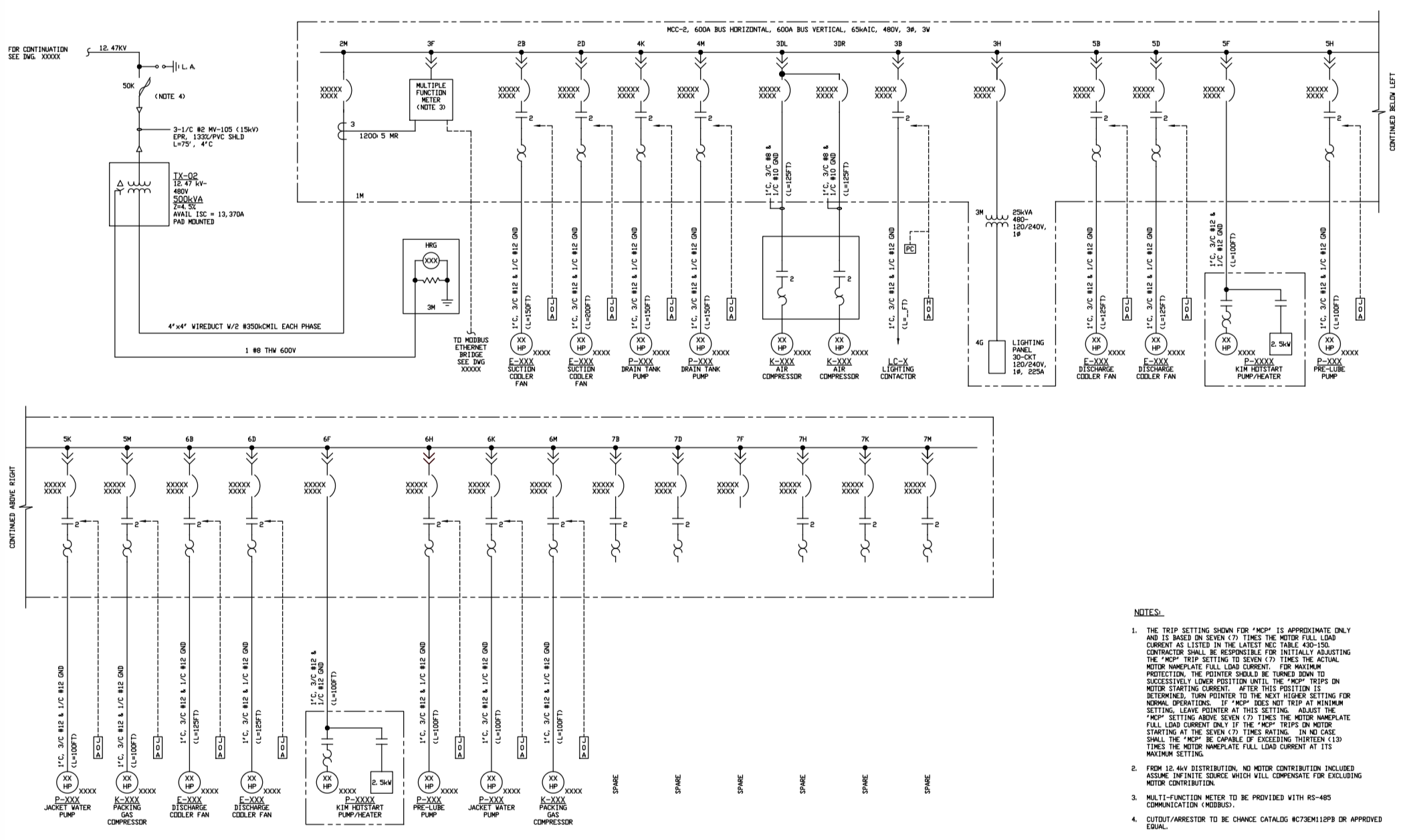
Circuit symbols are used in circuit diagrams (schematics) to represent electronic components. In the single line diagram, the system component is usually drawn in the form of their symbols. Circuit breakers are represented by. Lets go through a industrial single line diagram. Electric circuits can be described in a variety of ways. Lightning arresters are the protective devices used for protection of. Instead of representing each of three phases with a separate line electrical elements such as circuit breakers, transformers, capacitors, bus bars, and conductors are shown by standardized schematic symbols. Some of the standard symbols used to represent substation components are given in they are provided on each side of every circuit breaker. It is very versatile and comprehensive because it can depict very simple dc circuits, or a very we use universally accepted electrical symbols to represent the different electrical components and their relationship within a circuit or system. Elements location of a welding symbol | entity relationship diagram. Make sure you recognize these symbols. Circuit diagrams can be created with thousands of possible shapes electrical symbols are the most commonly used symbols in circuit diagramming. The circuit breaker, transformer, capacitor, busbar, etc.
Otherwise, there may be a fire. Single line diagrams are useful in planning a substation layout. Electrical circuit schematic symbols are graphical sign, that is used to design electronic, electrical circuit schematic diagram. Protection, circuit breaker and fuses symbols. The single line diagram is also called the blueprint of electrical system analysis.

This large circuit breaker is known as the main breaker, and it plays a crucial role in the electrical system by offering the means of disconnecting power to the. Your electrical panel is full of circuit breakers running through the panel, and the main circuit breaker serves an especially important function. The symbol for a thermal fuse used in any electrical circuit diagram. Lets go through a industrial single line diagram. Generator and transformer connections, star, delta and neutral earthing are indicated by symbols drawn by the side of the representation of these elements. Electric circuits can be described in a variety of ways. A final means of describing an electric circuit is by use of conventional circuit symbols to provide a schematic diagram of the circuit and its. Circuit symbols are used in circuit diagrams (schematics) to represent electronic components. A single cell is often called a battery, but strictly speaking a battery is two or more cells joined together. With the increasing emphasis on globalization, many industries are now looking to all parts of the world to produce, market, and sell their products. Symbol of the elements of electronic component used in circuit. They include both the full name, e.g. To provide simultaneous breaking on multiple circuits from a fault on any one, circuit breakers may be made as a ganged assembly.
They include both the full name, eg single line diagram symbols. Connectors symbol for electrical circuit.
Circuit Breaker Single Line Diagram Symbols: In the single line diagram, the system component is usually drawn in the form of their symbols.
0 komentar:
Posting Komentar